
Description
Product Overview
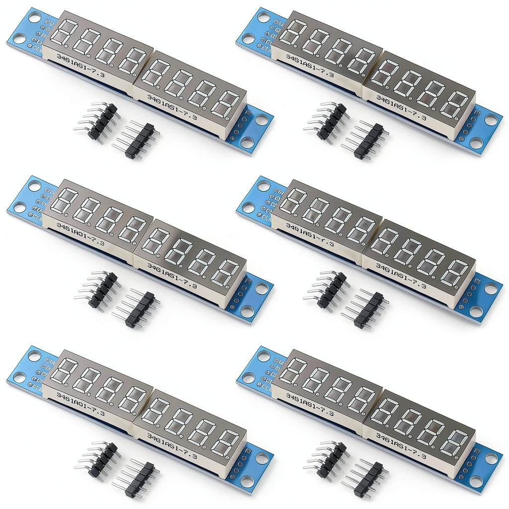
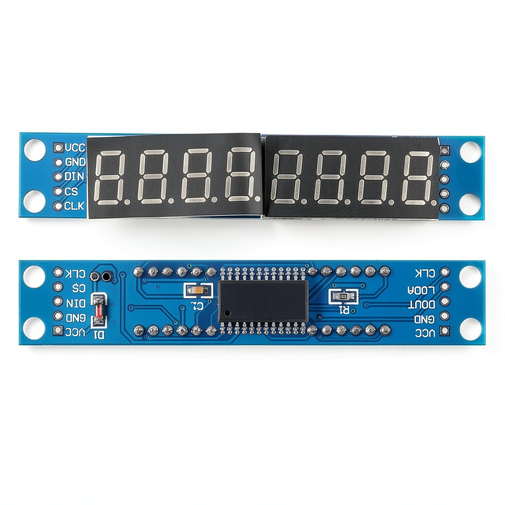
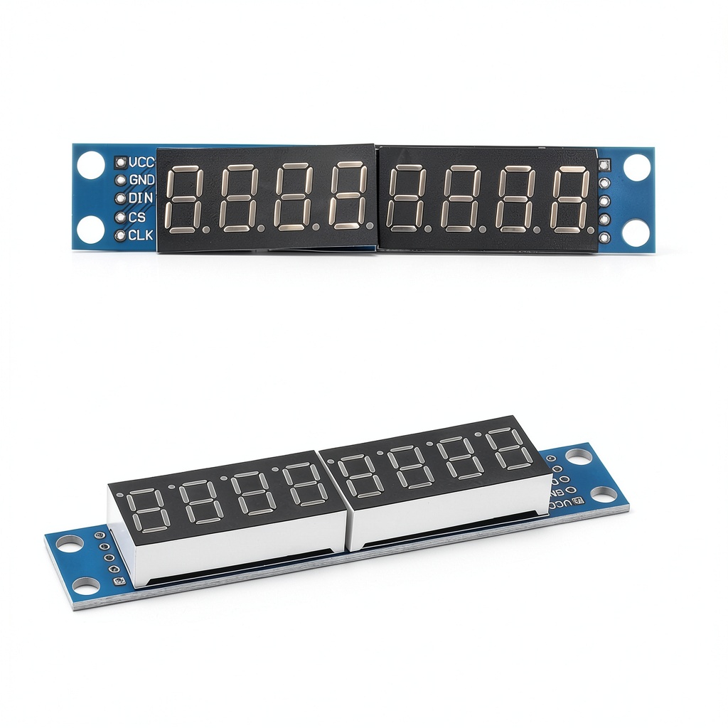
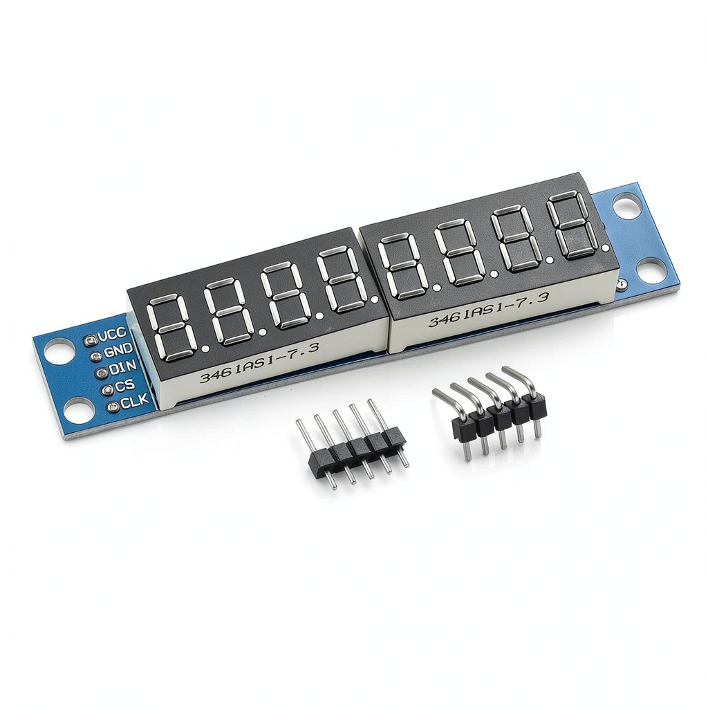
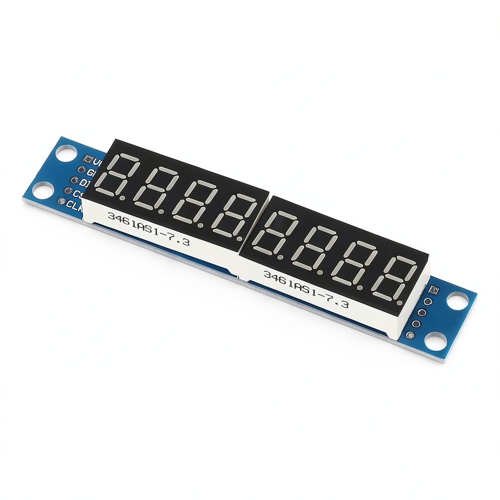
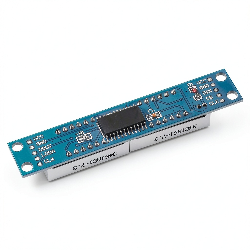
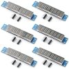
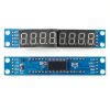
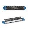
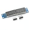
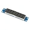
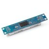
The MAX7219 8‑digit LED module pack of six delivers a versatile, high‑contrast 7‑segment display solution that integrates seamlessly with a broad spectrum of microcontroller platforms. Each module features a common‑cathode LED array, driven by the MAX7219 integrated serial input/output driver, which handles multiplexing, brightness control, and decoding internally. The compact PCB measures 4.84 × 4.02 × 1.1 inches and weighs just 2.89 oz, making it suitable for both prototype enclosures and final product housings. The design supports both 5 V and 3.3 V power rails, and only three I/O pins (DIN, CLK, CS) are required to operate up to eight digits, simplifying wiring and conserving valuable MCU pins. The modules are manufactured by AOICRIE, a reputable supplier in the optoelectronic displays market, and have earned a solid rating of 3.8 stars from 15 verified customer reviews.
Usage
These LED segment modules are ideal for a variety of applications where clear numeric readout is essential. Hobbyists can build digital clocks, temperature displays, and scoreboards with minimal code, thanks to the straightforward SPI‑like interface. In educational settings, the modules serve as hands‑on tools for teaching binary‑to‑decimal conversion, multiplexing concepts, and peripheral communication. Professional engineers often incorporate them into industrial instrumentation, such as voltage meters, process counters, and status indicators, where reliable, flicker‑free operation is critical. The modules are fully compatible with popular development boards including Arduino Uno, Mega, STM32 Nucleo, Raspberry Pi, ESP8266, and NodeMCU, allowing seamless integration into existing projects without extensive hardware redesign.
Why Choose Us
Choosing the AOICRIE MAX7219 module means selecting a product that combines proven silicon performance with thoughtful mechanical design. The MAX7219 driver chip is renowned for its low power consumption, built‑in current limiting, and automatic digit blanking, which together ensure long‑term reliability and reduced thermal stress. Each PCB is fabricated with high‑grade copper and a protective solder mask that guards against oxidation and short‑circuit risks. Quality control processes include functional testing of every module to verify correct digit decoding and brightness uniformity before shipment. Additionally, AOICRIE offers responsive technical support and a comprehensive documentation package, including wiring diagrams, example code for multiple platforms, and troubleshooting guides, empowering users to get up and running quickly.
Key Features
- Easy three‑wire connection (DIN, CLK, CS) reduces wiring complexity and saves MCU pins.
- Supports both 5 V and 3.3 V logic, making it compatible with a wide range of microcontrollers.
- Integrated MAX7219 driver provides flicker‑free, brightness‑adjustable displays without external components.
- Compact, robust PCB design ensures durability in both prototype and production environments.
- Responsive technical support and detailed documentation for fast development and troubleshooting.
FAQ
What microcontrollers are compatible with this module?
The module works with any 5 V or 3.3 V microcontroller that can provide a serial data line, such as Arduino, STM32, Raspberry Pi, ESP8266, and NodeMCU. Only three I/O pins are needed, so it fits even on boards with limited pin availability.
How do I control the brightness of the display?
Brightness is adjusted via the MAX7219’s internal intensity register. By sending a simple command over the serial interface, you can set the brightness level from 0 (off) to 15 (maximum) in incremental steps, allowing fine‑tuned visibility under various lighting conditions.
Can I cascade multiple modules for longer displays?
Yes. The MAX7219 supports cascading up to eight modules, enabling displays of up to 64 digits. Each additional module is linked by connecting the DOUT of one chip to the DIN of the next, and the same three‑wire bus controls all modules simultaneously.
Is there a risk of damaging the module if I connect VCC and GND incorrectly?
Connecting VCC and GND in reverse will damage the MAX7219 chip. Always double‑check the wiring diagram: VCC to the positive supply, GND to ground, DIN to the data line, CLK to the clock line, and CS to the chip‑select line. Using a pull‑up resistor on the MCU port is recommended if the port does not provide one internally.
What warranty or after‑sales service is provided?
AOICRIE offers a one‑year limited warranty covering manufacturing defects. If you encounter any issues, the support team will assist with troubleshooting, replacement, or repair options to ensure your project stays on schedule.
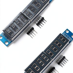
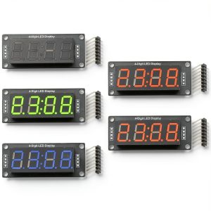
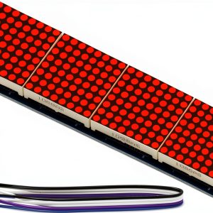
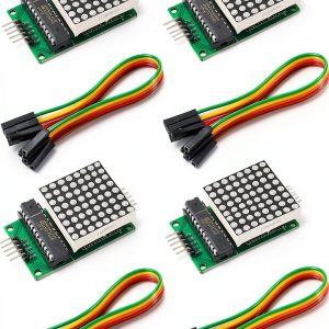 MAX7219 Dot Matrix Module 8x8 LED Display by ALAMSCN with 5 Pin Wires
Reviews
There are no reviews yet.